
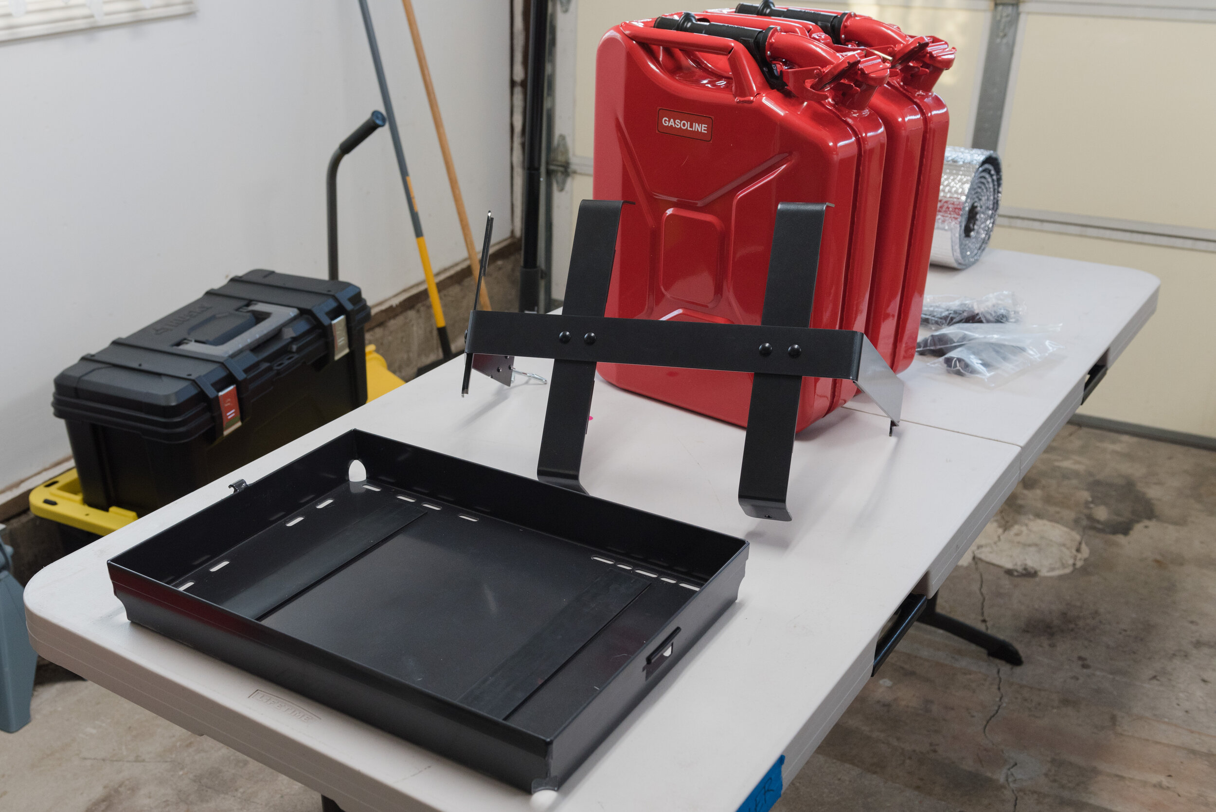
Here we go! Decided to install some Cali Raised LED goodies alongside the Switch Pros SP-9100 including:
42” slim single row light bar, includes single-relay wiring harness
Pair of side projecting pods as ditch lights, includes dual-relay wiring harness
Pair of 18W LED amber pods as chase lights, purchased additional dual-relay wiring harness
First I’ll discuss the installation of each lighting component then wrap up with (ha) with wiring to the Switch Pro power module.
Suggested tools/necessities include:
Set of allen wrenches
Two 1/2” box-end wrenches (ideally one ratcheting)
Wire cutters, stripper and crimper
14 gauge dual strand speaker wire
Heat shrink butt connectors and small ring terminals (I think #10 or 1/4” both fit)
Electrical tape
Pro-tips:
Blue Loctite all bolts after final fit.
Crimp all connectors and terminals tightly, then test-pull on the wire and connector to ensure a tight fit. Use a heat gun on all heat shrink. Wrap exposed heat shrink with black electrical tape, overlapping each wind by half the tape’s width. Total wrap should cover at least 1” before and after each connector. Stretch the tape while applying for maximum adhesion.
Disconnect battery before connecting lights to Switch Pros / bus bar, etc. Don’t risk shock.
Ask a friend to help with light bar installation.
Electrical Safety and You!
Whenever tackling a custom 12V electrical job, there are a few things we need to understand:
Safety first! Whenever wiring new circuits or modifying old circuits, be sure to disconnect the circuit you are working on from the battery. This could involve throwing a disconnect switch or removing connections from the main battery terminals.
If you are uncomfortable working with electricity or have never worked with wiring simple circuits, seek professional help. It is unlikely you will die from being shocked by a 12V car battery, though a burn is likely where current flows through your flesh. However, there is definitely long-term potential for incorrectly installed wiring to short-out (i.e. abrasion against rough metal surfaces over time), heat up, and cause a vehicle fire.
The Electrical Wiring Trifecta is: Amps, Length, Gauge (American Wire Gauge, or AWG).
Without going into too many technical details, it is important to first identify the amp draw of your circuit, then determine the length of wire used to provide said current, then use both to determine the appropriate wire gauge for installation using a wire gauge chart such as that provided by Blue Sea Systems. Note the total wire length should include the length of wire needed to connect the wire to the load (light) and load to the battery.
Let’s run through some scenarios!
The 42” slim single row light bar operates at 200W. The light will draw about 16A at 12.7V. The total circuit length connecting light bar and battery (or in my case, Switch Pro SP-9100 power module) is definitely less than 6 feet. This means I should use no lower than 14AWG to wire this light.
Pair of 18W LED amber pods as chase lights share the same circuit. This circuit will draw about 36W in total, or about 3A at 12.7V. The total circuit length is probably less than 20 feet. This means I should use no lower than 14AWG to wire these lights.
There are safety factors engineered into wire gauge charts and they have definitely changed over the ages. There is no harm in choosing a higher wire gauge for installation than needed. I could have chosen to install all circuits with 0AWG with no ramifications - in fact, this would have been better than 14AWG since larger gauge wires incur less voltage drop! However, the cost to install this wiring would have been astronomical… and it would have been difficult to splice into the factory wiring harnesses using 0AWG, haha.
Heat shrink wrap, heat shrink crimp-on terminals and electrical tape are your friend. Solder is not always needed, but is advised if you are only not using heat shrink crimp-on terminals. Solder acts as a conductor between the wire and terminal, and also acts as as a “glue” to provide structural support to the terminal and wire. Heat shrink has glue within the tubing that melts and provides structural support, which was good enough for me! Only solder in well ventilated areas. Common solder is a lead-tin mixture, that releases fumes harmful to your eyes and lungs when heated.
When wiring circuits exposed to the elements, it is best to select a dual strand wire that is also encased in either a UV resistant silicone or PVC shell.
Use Oxygen Free Copper (OFC) as opposed to Copper Clad Aluminum (CCA). CCA is essentially aluminum wire coated with copper, whereas OFC is pure copper. Overall, CCA is much less expensive than OFC. However, OFC excels at corrosion resistance (aluminum oxidizes in contact with air, has good flexibility and bend radii, has a higher current carrying capacity, and less resistance (therefore less power loss) per unit length of wire.
Not a safety factor, but fun fact - automotive wiring and batteries are not exactly 12V. A typical fully charged lead acid battery should measure about 12.6V as most car batteries are six 2.1V batteries connected in series. A “dead” battery is typically around 10.6V. Any voltage in-between is a partially-charged battery.
Additionally, your vehicle’s alternator applies a higher voltage to the battery when the vehicle is running to induce charging. Different alternators will regulate to different output voltages depending on whether the alternator itself is a standard or high output alternator, and whether the vehicle is running cold or hot. For our 5th gen 4Runners, the standard alternator should put out somewhere between 13.4V to 13.8V based on my limited observations.
Light Bar
Overall an easy install, but did run into a hiccup… The 42” light bar did not fit perfectly on the Southern Style Offroad Full Length Roof Rack - but I’ll get back to that in a bit.
The light bar includes its own single leg wiring harness and mounting brackets with hardware. However, the SSO wind fairing is specially designed for a pair of mounting brackets that were provided by SSO with the rack. The SSO mounting brackets only included the necessary hardware to fasten the mounts to the wind fairing, which thread into t-nuts welded into the back of the mounting brackets. I used the socket-head bolts provided with the light bar to mount the light bar to the SSO brackets. Only two of the four bolts on each mounting bracket will attach to the wind fairing as they’re drilled for different length light bars.
It is necessary a helper install the light bar. My wife gave a hand and we quickly determined that the light bar was in fact too short for the mounting bracket to line up properly with the holes in the wind fairing… by a fraction of an inch. The easiest fix was adding two flat washers on each side of light bar (see photos below). This pushed out the brackets far enough on each side so they nuts lined up properly.
Ditch Lights
Very easy install, though hood is a little crooked with a slightly larger gap on one side than the other (I need to fix this…).
The ditch light kit includes a dual-plug wiring harness and mounting brackets with hardware for the pods to attach to the Cali Raised LED Low Profile Ditch Light Mounts (purchased separately). Note that Cali Raised LED provides shorter bolts (with nylock nuts) to mount the pods to the ditch light mounts as the original bolts are too long. Their ditch lights are truly low-profile!
First, assemble the LED pods and mounting brackets by inserting the nut(s) and washer(s) in the pod’s channels (see photo), and thread the socket-head bolt through. This takes some dexterity, and requires one hand/finger to hold the nut/washer in place while using the other to tighten the bolt.
Afterwards, install the pair of ditch light brackets onto the hood bracket. Install one side first before moving onto the other. The steps are:
Using 12mm socket, fully remove front-most bolt from the hood bracket.
Re-install front-most bolt through front-most slot in ditch light bracket, but do not tighten all the way! The ditch light bracket should still be allowed to rotate around the bolt (i.e. fully tighten then back off a turn or so).
Fully remove the rear-most bolt, then swing the bracket into place. Reinstall rear-most bolt and tighten both bolts. I couldn’t find any torque specs, so I tightened hand-tight plus a quarter turn.
Once the ditch light brackets are mounted, use the supplied bolts and nylock nuts to fasten the LED pod to the bracket. This requires at least two 1/2” box-end wrenches (ideally ratcheting wrenches). I aimed the pods mostly towards the sides to minimize hood glare - besides, they’re “ditch” lights, not hood lights.

Chase Lights
Assembling the chase lights are similar to the side-shooter LED pods. Installed these using t-nuts, studs, and nylock nuts to the rearmost crossbar on the roof rack.
Wiring Everything
Need to go take more photos of this - will hopefully update soon. Just finished cleaned up my wiring using stick-on zip tie mounts, which were affixed to the inside of the roof rack’s structure… so a lot neater now!
Basically, here is how I connected each light to the Switch Pros’ power panel in the engine bay:
Use provided single-leg wiring harness to connect light bar to power panel. Ran wiring alongside driver’s side windshield cowling. This wire runs alongside two other wires (one for driver’s side scene lighting and one for chase lights), which were eventually all tightly bundled into a single strand using black electrical tape. Overall wire length was too long; cut wiring harness to length (removing relay and switch), and crimped on ring terminals to connect to power panel.
Used provided dual-plug wiring harness for ditch lights. Ran wiring underneath cowling (shown below) on each side of vehicle. Ran wiring from passenger-side ditch light along pre-existing wiring on engine firewall, using zip-ties to hold in place. Overall length was too long; cut wiring harness to length (removing relay and switch), and crimped on small ring terminals to connect to power panel.
Purchased additional dual-plug wiring harness for chase lights. Ran wiring alongside driver’s side of roof rack, and eventually alongside driver’s side windshield cowling. Used stick-on zip tie mounts to hide wiring. Overall wire length was too short; cut wiring harness to remove switch relay and switch, then added appropriate length of 14 AWG wire with small ring terminals to connect to power panel.
Have not yet had a chance to use these lights to their fullest extent, yet. Hoping to spend more nights out later in the fall when it cools down.


